
Geometric dimensioning and tolerancing shortly written as GD&T, is a language of symbols that is used to convey the intent of the object design along with its geometric shape, size and the location of its various features. Their study is a science known as symbology.
The present article considers those symbols within the scope of GD&T that specify the geometric characteristics and dimensional requirements of the industrial engineering drawings as per standard: ASME Y14.5M-1994.
What is Geometric Dimensioning and Tolerancing?
Geometric dimensioning and tolerancing is defined as:
The method consisting of symbols that are used in engineering and production operations to communicate design specifications (specific to geometry) and tolerances is known as GD&T. It offers a more precise horizon for controlling the geometry of features on a part.
In short, it employs a system of symbols to write the geometric tolerance.
It is used in conjunction with the traditional linear dimensioning method to fully articulate the form, orientation, and location of features.
Difference between the traditional dimensioning and tolerancing technique and GD&T?
The geometric dimensioning and tolerancing technique provides the means to design and manufacture parts keeping in view the exact function and relationship between different features of the same part or between the two different mating parts.
From this one can imply that a good design is not just about stating dimensions and tolerances alone. It goes much beyond it. In contemporary dimensioning and tolerating methods such as GD&T, the designer is to think in terms of the intended function of the part and how its various design features are going to affect that function.
The figure shown below illustrates the dimensions and tolerances of the part using traditional techniques. Reading this drawing fails to provide the relationship between the pin and the plate. On this, one might ask: is the pin perpendicular to the plate, and if so, then to what degree? Which surface is to be referenced for measuring the perpendicularity of the pin?
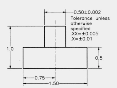
The use of this drawing is risky as it is vulnerable to multiple interpretations based on intuition and experience. One can fairly proclaim that the present drawing is silent to answer the posited questions in a perfectly ascertaining way. Then, what is next? Any solution? Yes! GD&T offers a smart solution in the product design process in the guise of its symbiological universe.
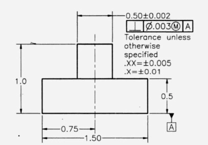
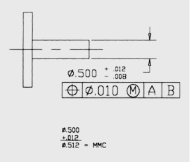
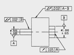
The figure shown below is re-dimensioned but now using GD&T. The feature control frame (connecting rectangles/boxes) contains the pearls of precious information: the reference plane (datum A), the geometric relationship between the pin and the plate, and the permissible deviation in the perpendicularity of the pin to the reference plane. Everything is now crystal clear. Aren’t the chances of error lower than before?
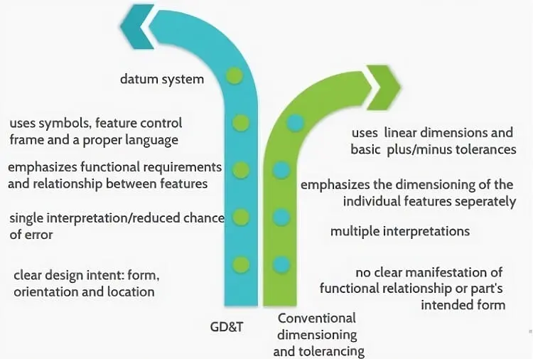
The key differences are summarized in the figure below.
Feature Control Frame
It is the essence of GD&T. It consists of a series of connected rectangles. As shown in the figure below, the first box consists of a geometric characteristic symbol that designates the part’s geometric shape.
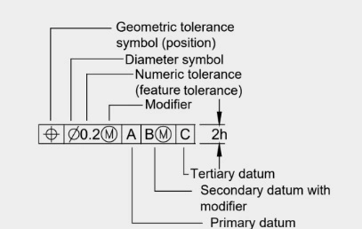
The second box consists of the numerical value of the geometric tolerance. It may also contain modifiers, where necessary. For example, in the example of the control frame cited above, the symbol designates that the tolerance has a circular or geometric pattern; whereas, the encircled M symbolizes a modifier known as maximum material limit (MMC)- a concept which shall be discussed a little later.
The next three boxes refer to the datum designations: the first box is for the primary datum (A), the second for the secondary datum (B), and the third for the tertiary datum (C).
Let’s discuss two examples of the feature control frame to demystify this vital concept.
- Consider a simple feature control frame.
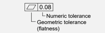
It reads that the surface should be flat within the tolerance of 0.08mm. Since it does not require measuring flatness by referring to the datum, the datum boxes are omitted.
- Find below another control frame.

It reads that the surface must be perpendicular within the tolerance of 0.05 mm at MMC to datum A.
Geometric Characteristic Symbol
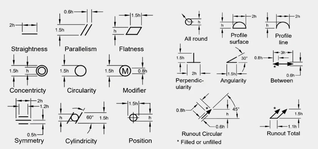
The figure below illustrates many geometric symbols associated with GD&T. The first column demonstrates the geometric symbol, the second column reads the geometric description, the third column divides the symbols into five categories such as form, profile, orientation, location, and runout, and finally, the fourth column categorizes the symbols based on tolerance. It is important to note that the first category of tolerance (individual features) does not refer to datums (for referencing measurements).

The figure below shows the dimension of each geometric symbol based on the lettering height “h”.
Furthermore, the figure shown below illustrates some of the other symbols used in the GD&T system, that are integrally used with the conventional system. Likewise. all the dimensions of symbols are demonstrated on proportions based on lettering height “h”.
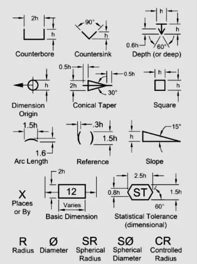
Two unique symbols in the above-shared picture are the basic dimensioning and statistical tolerancing symbols: A basic dimension refers to the theoretically determined perfect size, location, or orientation dimension. The unique characteristic is the box in which the basic dimension is written; whereas, a statistical tolerance symbol is designated by an elongated hexagon surrounding the capital letter “ST”. Statistical tolerance here refers to the determination of the size tolerances using statistical process control (SPC) methods.
Modifiers
They refer to a concept that further defines and refines the geometric characteristics of a part under the GD&T system. They are added to the basic characteristic symbol to convey additional information about tolerance or control requirements. As their name implies, they modify a specified tolerance.
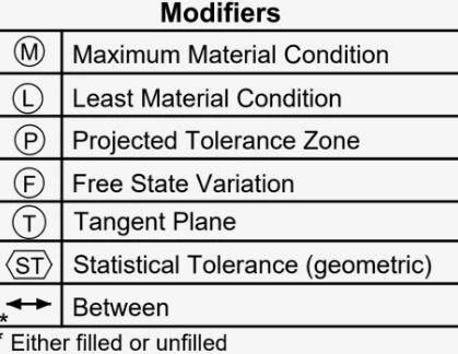
Some of the key modifiers used in the GD&T are tabulated below.
Let’s discuss each one individually.
- Maximum material condition (MMC): designates that the tolerance applies when the part contains the maximum amount of the material of which it is made. For a hole, MMC is the smallest diameter of the feature of size, while for the shaft it is the largest diameter of the feature of size. MMC for the shaft is shown below.
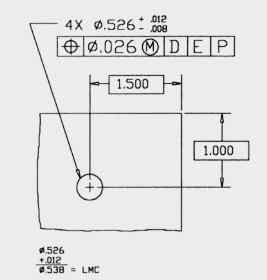
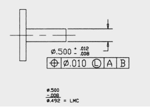
- Least material condition (LMC): designates that the tolerance applies when the part contains the minimum amount of the material of which it is made. For a hole, LMC is the largest diameter of the feature of size, while for the shaft it is the smallest diameter of the feature of size.
LMC for a hole is shown below.
LMC for a shaft is shown below.
- Regardless of feature size (RFS): designates that the tolerance applies irrespective of actual feature size yet within the limit of size. RFS specified at only MMC or LMC would be applicable only at those conditions.
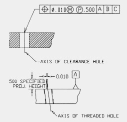
- Projected tolerance zone (P): designates that the tolerance zone goes beyond the surface. The figure below shows how it applies.
- Tangent plane (TP): designates that the tolerance applies at the tangent plane only, rather than the whole surface.
- Full indicator movement (FIM): designates the instrument tool such as a gauge or an indicator must traverse through the entire tolerance zone during its inspection. It shows that the dial indicator needle while traveling through 360 degrees, must not exceed the tolerance limit.
- Free state (F): designates that the tolerance applies when the part is in its free/unstressed state.
- Statistical tolerance (ST): designates that the tolerances (or more precisely the tolerance limits) are calculated using statistical methods such as standard deviation or probability distribution.

- Basic Dimension (B): designates the theoretically exact dimension. It has geometric tolerance by a special note on the drawing.
- Datum feature simulator (S): designates the part as if it were a datum part. Or, it mimics the part for a datum part.
- Simultaneous requirement (SR): denotes that the two or more features are to be controlled together.
- All around Ⓛ: designates or specifies the applicability of the tolerance around the whole circumference of a cylindrical feature.
- Total runout Ⓡ: designates that the specified surface/feature must lie completely within the tolerance zone.
- Profile of a surface Ⓟ: designates a 3D tolerance zone that controls the shape of a surface.
- Concentricity ⓒ: designates a tolerance zone within which the axil of the feature would lie.
- Symmetry Ⓢ: denotes that the feature is symmetrical about a specific axis/plane.
- Circular runout Ⓛ: designates that the circular elements of a feature would lie entirely within the tolerance zone.
Merits of GD&T
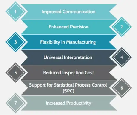
One of the biggest advantages of using GD&T is that being an international language of symbols it rids the practice of drawing notes for reading the drawing. It is a vehicle for instant communication of the design intent. Its other productive aspect is that its language is universal and therefore there is only one interpretation of a single drawing whichever country it is read. It supports production-related operations in terms of reduced time and mental labor. Its other merits are shortlisted below in the figure.
Demerits of GD&T
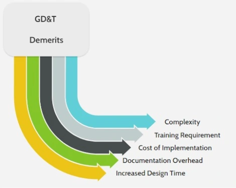
The use of GD&T requires first to get some basic education which marks its first demerit. It is somewhat a complex and comprehensive language that requires serious heed in the beginning otherwise there is a great likelihood of confusion and misunderstanding from the engineer down to the machinist. There is a minimal cost of implementation required as well. Moreover, some organizations are resistant to implementing it due to the less flexibility it offers than the traditional method of tolerancing and dimensioning. Its possible demerits can be summarized below.
Applications of GD&T
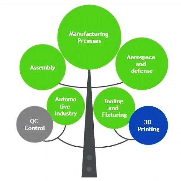
There are numerous applications in which the system of GD&T is used. Its primary domain is mechanical engineering or mechanical part design and manufacturing with improved functionality, precision, and assembly. The industries in which its use is frequent include automotive, aerospace and defense, medical, electrical, and electronic industries, among others. Its area of application is rapidly getting wider on account of its error-proof structure of dimensioning and tolerancing.
Frequently Asked Questions
What is Geometric dimensioning and tolerancing?
It is shortly written as GD&T. Compared to the conventional dimensioning and tolerancing system, GD&T refers to a new system that controls part’s features very precisely. It makes use of the feature control frame to demonstrate part dimension and tolerance. Its particular language is a language of symbols.
What are the geometric characteristic symbols used in GD&T?
The geometric characteristic symbols used in GD&T include straightness, flat, circularity, cylindricity, the profile of a line, the profile of a surface, angularity, perpendicularity, parallelism, circular runout, total runout, position, concentricity, and symmetry, among others.
What is the feature control frame used in GD&T?
It consists of connected rectangles or boxes and comprises a geometric tolerance symbol, its numeric value, modifier, and datum.
What are the modifiers used in GD&T?
They designate special information to the part feature. As their name implies, they can modify the value of the tolerance within the size limit. The most commonly used modifiers include maximum material condition (MMC) and least material condition (LMC).
What are the merits and demerits of GD&T?
Its merits include improved functionality, high precision, reduced chances of error, and unit interpretation among others. Its demerits entail training, high cost of implementation, increased design time, and others.
I am the author of Mechanical Mentor. Graduated in mechanical engineering from University of Engineering and Technology (UET), I currently hold a senior position in one of the largest manufacturers of home appliances in the country: Pak Elektron Limited (PEL).