Engineering drawing is a universal language of engineers; that is, irrespective of your national identity in the world, the engineering drawing made in one country is easily readable and understandable by any other person in the world trained in this language.
As it represents precise information about the object of engineering concern, no one can misinterpret it due to the universalizability of its syntax. Therefore, any engineer from the U.S.A. to China, Japan, and South Korea would extract the same meaning regardless of the national boundaries they live within.
What is Engineering Drawing?
Engineering drawing has its roots back in 500 BC in the regime of King Pharos in Egypt, where symbols were used to visualize objects of scientific concern. Strictly speaking, an engineering drawing is a graphic visualization of an engineering object. It has its unique syntax and lexicon. It makes use of symbols that are standardized to convey precise information to its global reader.
Why Engineering Drawing?
In the great old days, engineering drawings were used to represent structures and objects, both new and old graphically. The drawings of existing machinery were employed for creating new machinery with optimal design.
Over the period, these drawings established their decisive role in engineering design matters which led to the development of special computer software and programs to draw these drawings in their 2D or 3D guises.
These software include Autodesk, Matlab, Inventor, SolidWorks, Fusion 360, and others, which are well explained in our article titled Types of CAD Software.
Engineering drawings are important in developing objects, structures, or machinery that involve several assemblies or sub-assemblies. In that case, the graphic language of the drawing would help manufacturing engineers align their operations according to the drawing drafted by the CAD engineer or a draftsman.
Suppose the drawing is clearly and correctly drafted as per the standard conventions and rules of the game. In that case, it will invoke only a single interpretation, thereby keeping its reader from any confusion that might otherwise cause the loss of precious time and unnecessary mental labor.
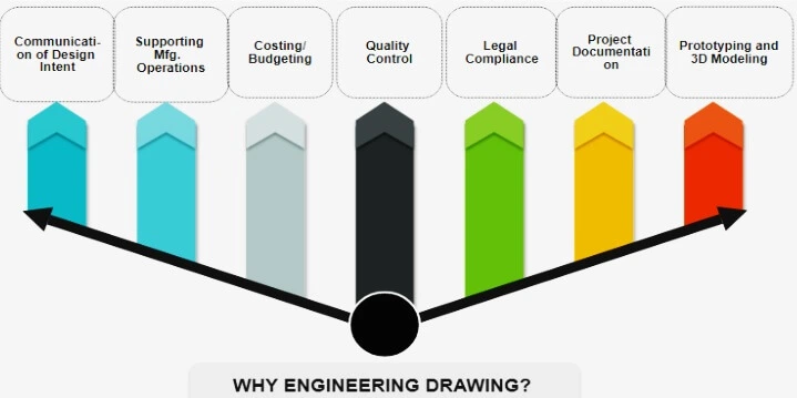
Its other major uses include better conception and visualization, quick surveying, budgeting, risk assessment, project planning, quality control, and others. These are summarized in the illustration below.
The present article is dedicated to the engineering drawings that come within the environs of mechanical engineering. Or, more simply, the present article exclusively concerns mechanical engineering drawing or CAD engineering drawing.
Classification of Engineering Drawing
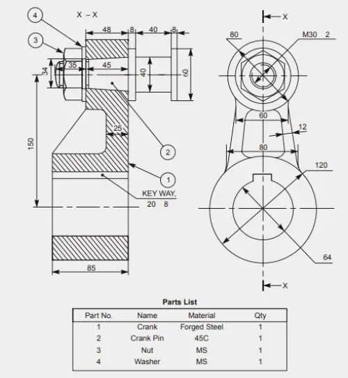
Machine Drawing
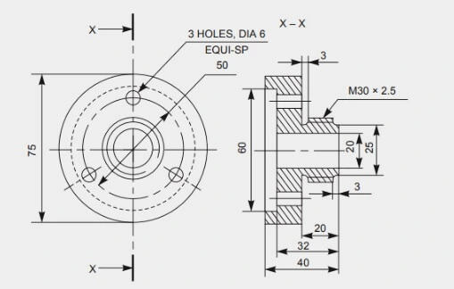
As its name implies, it refers to the machine parts or components. In this drawing, in addition to 2D, the 3D views of the part are also mentioned to make the machinist fully understand the drawing in terms of the size and geometry of the part. A classic example of a machine drawing is illustrated below.
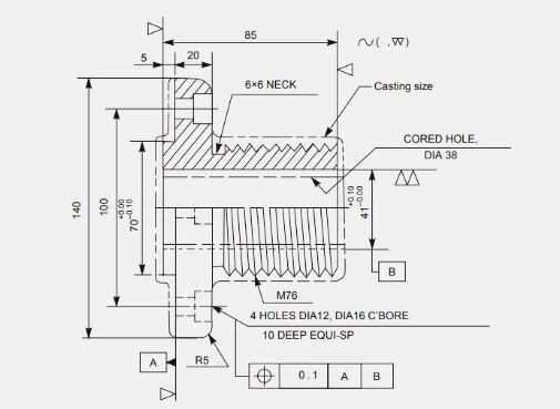
Production Drawing
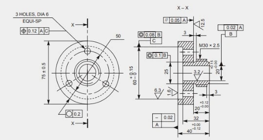
It is a drawing that guides the craftsman on the shop floor in producing the intended object. It is also called the working drawing that includes dimensions, limits, tolerances, and special processes, such as heat treatment operations, honing, lapping, and surface finishing processes among others. It may include other relevant information as well, such as the product’s name, the number of products to be made, and so forth (Figure below).
Part Drawing
As obvious by its name, the part drawing is the detailed drawing of a part or a component of a complex machine. If it is provided with the part’s name and its production quantity, it would be known as the production drawing.
In the part drawing, all the principles of the orthographic projection are fully utilized to adequately pass on the part’s size and geometry to the craftsman.
Assembly Drawing
It refers to the drawing that describes the correct location of the various components of a machine to be assembled.
There are different forms of the engineering assembly drawing as follows.
Design Assembly Drawing
It shows the design layout of a machine. When a machine is designed, its design assembly drawing would mean a drawing that would read to its overall design, including various parts, their shape, clearances, and alike.
Detailed Assembly Drawing
Suppose the machine is made of a few simple parts. In that case, the detailed assembly drawing designates the representation of such parts in the correct sequence of assembly, including dimensions, tolerances, and others on a single sheet of paper.
Separate views of the sub-assemblies can still be prepared if required with a clearer understanding of close assembly details such as fitting and so on.
Sub-Assembly Drawing
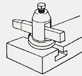
An assembly drawing that shows the explicit view of the sub-assembly of an assembly unit is called a sub-assembly drawing. Machines such as lathes, slotters, and milling presses, as well as cars, air-liners, turbines, and so forth, are made of several pre-assembled units called sub-assemblies. They may include tailstock in the lathe, carburetor in a car, the fuselage of an airliner, and alike. Their drawings come under the name of sub-assembly drawings.
The figure below shows the sub-assembly drawing of the lathe’s tool post.
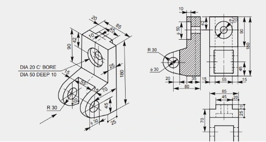
Another example of a sub-assembly drawing of a sliding block is shown below.
Installation Assembly Drawing
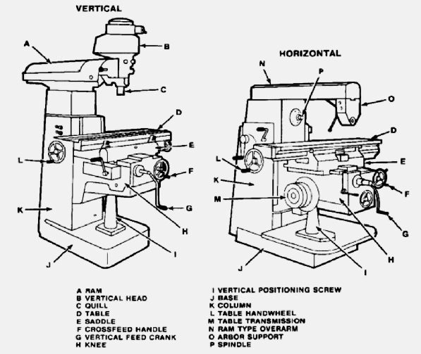
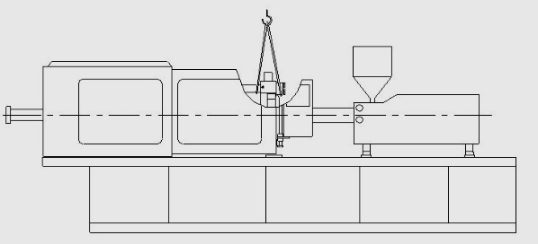
It is used at the time of installation of a new machine. It guides which part of a machine is to be assembled where. It shows the correct working sequence of the various parts of a machine to be assembled. It may include the dimensions/tolerances/types of fit of some outer parts as well. For example, the installation diagram of a milling machine would show its various parts, such as a table, ram, base, column, saddle, spindle, and others, in a correct assembling manner.
Another example is the injection molding machine, as shown below.
Assembly Drawing for Catalogues
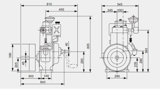
This is the assembly drawing of a machine that mentions the correct size and dimensions of its several mating parts. It is cataloged for the potential buyers of the machine for the quick assessment of space required and the foundation to be constructed for that machine (Figure below)
Assembly Drawing for Instruction Manuals
When a big machine is to be shipped away, then it is first disassembled where it is manufactured and reassembled where it is sent. The assembly drawings that are used in this regard fall in this category. These drawings have each part uniquely numbered for each job. The figure shown below is the assembly drawing of the drill press for the instruction manual use.
Exploded Assembly Drawing
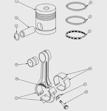
As its name implies, it shows the exploded view of a machine’s part in its instruction manual, where different parts of that machine are enlisted in the part list section. The figure below shows one such drawing in which sub-assemblies of a part are shown in a real assembling sequence without getting assembled.
Schematic Assembly Drawing
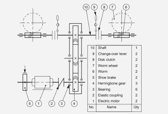
It is the assembly diagram of a machine that helps understand its operating principle. From the assembly drawing, it is sometimes very difficult to understand its operating principle. In that case, the schematic diagram is usually very supportive as it replaces the sub-assemblies with their schematic symbols for quick learning (figure below). The figure below shows one such drawing for a gearing system.
Machine Shop Drawing
After the casting and forging operations, the part now comes to the machine shop for machining. Here, it is machined to the right size as per dimensions according to the machine shop drawing (figure below). It is a separate drawing for every subsequent machining process and may accordingly include forge shop drawing, pattern shop drawing, sheet metal drawing, and so forth.
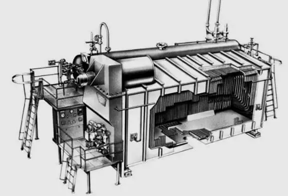
Patent Drawing
When a new machine is invented, the drawings that represent such a machine are called patent drawings. It is characterized by the pictorial representation of the machine for quicker understanding. It is of pressing need to accurately mention all the dimensions, tolerances and fits in the patent drawing. The figure shown below is the patent drawing of a single burner D-type foster wheeler boiler.
Frequently Asked Questions
What is an engineering drawing?
Strictly speaking, an engineering drawing is a graphic visualization of an engineering object. Its primary focus is to communicate the intent of the engineering design of a machine or structure.
What engineering drawings are used?
They are used to convey necessary information about the object’s design. Their other uses are found in costing or budgeting, product life cycle management (PLM), risk assessment, quality control, product planning, and production planning, among others.
What are the two methods of engineering drawing?
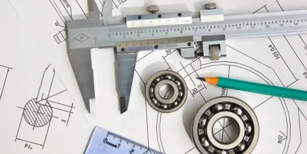
There are two: one is the use of conventional means, such as the method of manual drawing using paper, pencil, ruler, board, calipers, etc.; the other is the use of computer software that helps in the making of such drawings. These software or computer programs are known as CAD software.
What are the main types of engineering drawing?
There are four types of engineering drawing: Machine drawing, Part drawing, Production drawing, and Assembly drawing.
I am the author of Mechanical Mentor. Graduated in mechanical engineering from University of Engineering and Technology (UET), I currently hold a senior position in one of the largest manufacturers of home appliances in the country: Pak Elektron Limited (PEL).