There are multiple opportunities based on which industrial robots are classified. These classifying criteria range from the geometry and coordinate system to the degree of freedom, control system, and programming language, among many others.
It is significant to state that the selection of a robot based on any one of the benchmarks mentioned above is a critical job. Two robots that are constructed to possess two different control systems yet similar degrees of freedom and coordinate systems would not perform identical tasks.
It signifies that the choice of a robot for a particular industrial application means integrating the desired structural features of a robot system to make it operationally aligned with the current industrial need.
Classification by Geometry and Coordinate System
Based on the coordinate system, the robots are classified into four categories as follows:
Cartesian-coordinate Robots
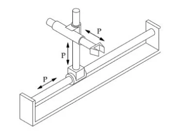
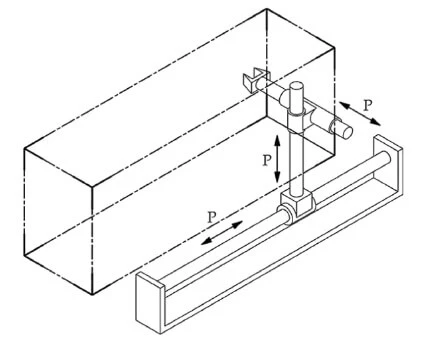
In these robots, the manipulator moves along three linear, mutually perpendicular axes. That is, the robot arm can be programmed to move up or down, in and out, and in a direction perpendicular to the plane in which the preceding two motions take place, as shown above. The working envelope is the parallelogram with its sides as maximum arm strokes along the X, Y, and Z axes, as shown below.
Cylindrical-coordinate Robots
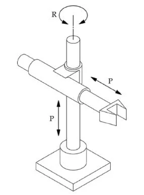
Similar to the cartesian type, two of the robotic arm’s motions are along the two linear (cartesian) axes, while the third rotary motion is along a vertical axis, as illustrated above.
Or, more precisely, the robotic arm can move up and down, in and out, and can swing around a vertical axis. The figure below shows the working principle of a cylindrical robot with its working envelope, which is a hollow cylinder.
The external diameter of the envelope shows the maximum stroke of a robotic arm. In contrast, the inner diameter is the distance from the gripper to the vertical axis when the arm is fully retracted.
On account of its robust structure, its load-carrying capability is higher, and therefore, it is popular in applications where heavy objects are to be handled in industry.
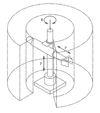
Polar-coordinate Robots
These robots are also known as spherical-geometry or polar-spherical-coordinate robots. The motion of the romantic arm is along the three axes: two motions are rotary, while one is linear.
Or, more precisely, the robot’s body can pivot in either a vertical or horizontal plane or both, and its arm can accordingly be extended out and retracted. The figure below shows a polar-coordinate robot and its working envelope.
It is noteworthy that the working envelope is the section between the overlapping volumes of two concentric spherical geometries. The radius of the outer sphere is the maximum stroke of the arm along the linear axis. In contrast, the radius of the inner sphere is the shortest distance of the end-effector or gripper to the vertical axis when the arm is fully retracted.
They find their industrial applications in the loading and unloading of the machine tool.
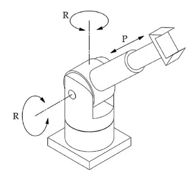
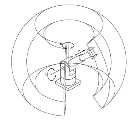
Articulated-arm Robots
These robots are equipped with a series of linkages and rotary motions to produce humanlike motions. Their parts and motions are easily referred to as the human arm. It is shown schematically below, along with its envelope.
The versatile geometry of the robot enhances its reachability due to which they are popular in terms of their high precision and continuous path robotizability.
They find their applications in MIG welding in many industries. Its reachability can be further increased by mounting it overhead.
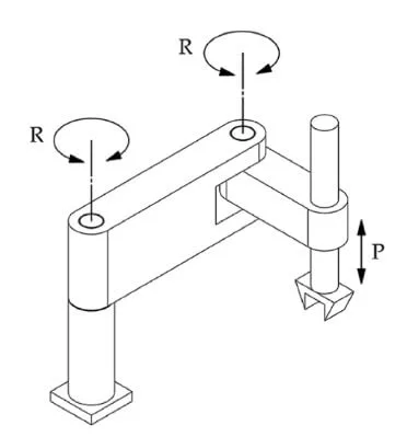
Classification by Degree of Freedom (DOF)
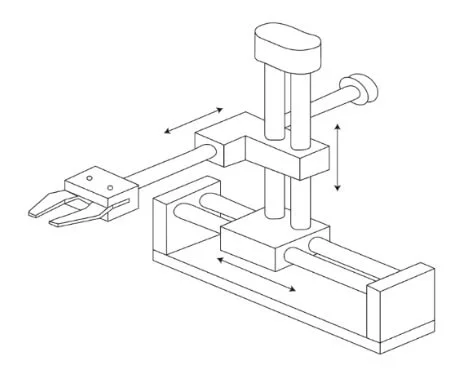
The degree of freedom is commonly referred to as the number of linear and or rotary axes of motion. Industrial robots may have three, four, five, and a maximum 6 degrees of freedom. The robot shown below has a degree of freedom of three.
It is noteworthy to add that the motions along two parallel linear axes cannot be counted as two degrees of freedom. Likewise, the two rotary motions along a common axis do not refer to two degrees of freedom. In either case, one of the two motions or axes is redundant in the calculation of the overall degree of freedom.
A robot’s highest degree of freedom is six in most cases (although robots with as high DOF as 8 are also commercially available). It means that there are three linear motions along three orthogonal linear axes and three rotary motions, each round one of these linear axes.
The higher the DOF of a robot, the more versatile it is in emulating the human operator (the anthropomorphic arm).
A robot with six DOFs is, therefore, more versatile in terms of having an ensemble of linear and angular motions; that is, three linear arm and body motions and three wrist-like rotary motions.
To increase the working envelope of a robot, it is sometimes mounted on a rail or gantry. Doing so does not add up any DOF to the robot. However, it does expand its workspace.
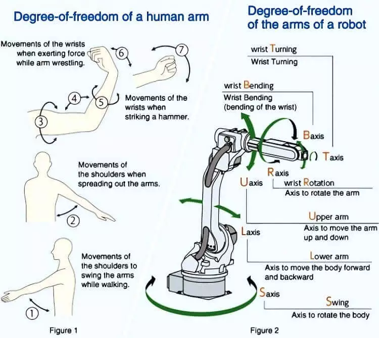
The figure below shows the similitude of DOF between a human arm (figure 1) and an industrial robot (figure 2).
Classification by Control System
Based on the control system, the robots are classified thus:
Nonservo-controlled Robots
These are robots that fall under the first two categories of the JIRA definition of robots we stated in our article “What is an industrial robot?” They are simple in design and construction, give a fair economy, easy to program and operationalize. They give adequate dimensional precision.
In its construction, the nonservo-controlled robot consists of a mechanical unit called a manipulator and a control unit. The mechanical unit is possessed to have moving parts that perform the programmed task.
They are mainly air-powered, though their hydraulic counterparts are also equally effective. They operate with the mediation of transporters along a cartesian coordinate system on a point-to-point basis.
These various points are fixed throughout a cycle by mechanical or electromechanical stops. The actual path between the mentioned points cannot be defined or controlled.
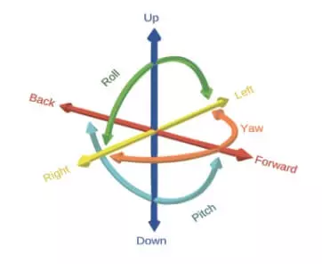
The angular motions such as roll, yaw, and pitch along one or multiple axes are provided by rotators. Along a single axis, the motion is controlled via a single command: on or off. It is thus because the mechanical stops determine the starting and ending points of the stroke only.
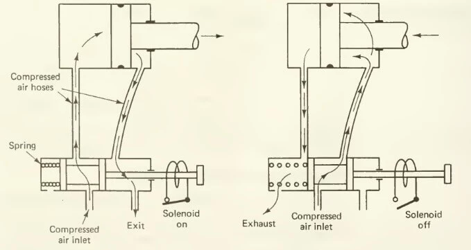
The command on/off is controlled by a four-way actuated solenoid valve that, in turn controls the flow of compressed air through the two inlet ports of a double-acting cylinder of the transporter, as illustrated below.
The left figure shows the working principle of a solenoid-actuated valve during the stretching of the robotic arm, while the right figure shows the same during the retraction of the arm.
Servo-controlled Robots
The servo-controlled robots are the typical NC and CNC machines. They are further grouped into two: one is called the point-to-point robots, similar to the NC positioning machines, and the other is known as continuous path robots, identical to the NC contouring machines.
In the point-to-point robots, the path of the gripper cannot be defined. The gripper, however, can be stopped at any one of the infinite points within the working space (envelope) of the robot.
It is contrary to the point-to-point nonservo robot in which electromechanical stops are to be added to define the desired points that are not included in the program. It evidences that the control unit of a servo-controlled robot and the MCU of an NC machine are the same.
Moreover, similar to an NC machine, the servo-controlled is provided with a feedback system to detect any deviations from the path programmed.
To drive the manipulator of a point-to-point servo-controlled robot, a hydraulic power source is used due to its cheaper economy and high power density.
This robot is characterized by its high load-carrying capacity and elongated working range. Its programmable language is easy since it encompasses a word-address format similar to that of an NC machine.
Whereas, the continuous-path robots are provided with immense capabilities and industrial opportunities. Its manipulator can be driven along a controlled path as programmed by avoiding any obstacles on its way.
Similar to the NC contouring systems, its control unit is equipped with a microcomputer and software responsible for carrying out linear and circular interpolations.
Not only does the feedback system continuously monitor the position but also the velocity of the manipulator after a short period. Therefore, these robots give higher precision and repeatability.
But, they tend to be smaller in size due to which their load-carrying capability is not very much. In the modern continuous-path robots, the hydraulic power source is replaced by electric motors and drives to eliminate problems related to oil spillages which require floor mopping or preventive maintenance.
Classification by Method of Programming
The nonservo and servo-controlled robots are programmed differently. The nonservo-controlled robots, as described above, operate on a programmable controller that gives a sequence and duration of on/off command to each axis of motion and in which a mechanical or electromagnetic stop is used to determine the final point on each axis.
Whereas, as also articulated in the preceding section, the controller of a servo-controlled robot is similar to that of an NC or CNC machine thereby rendering programming methods virtually almost alike.
Keeping in view the brevity (shortness) of space, let’s discuss three different methods of programming a servo-controlled robot concisely.
Walk-through Programming
In the walk-through programming method, the operator teaches the robot by feeding the programmed instructions to the robot’s controller.
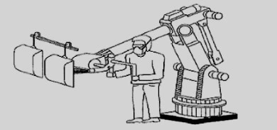
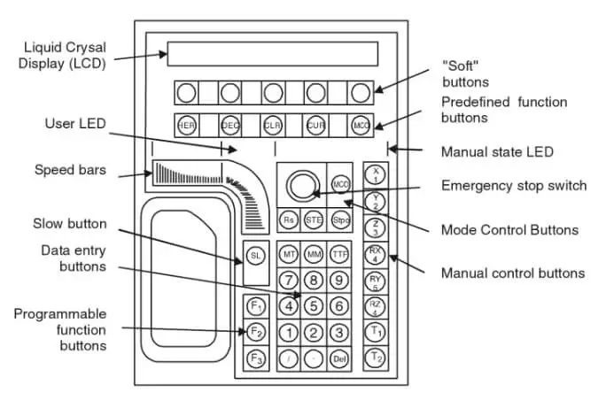
Actually, the robot operator manually drives the manipulator (the robot’s body) by a hand-held pendant, as shown below, through pre-set instructions such as positions, speeds, and so forth and thereupon teaches the robot these fed instructions by pressing the teach button on the pendant once the manipulator performs the desired action.
Likewise, grippers or end effectors are also programmed at the desired position of operation using an auxiliary function command.
Hence, when the entire cycle of correct events is accurately stored in the memory (control unit) of a robot, the robot is ready to finally work by repeatedly performing the desired motion cycle over and over again when subject to a playback. This programming method is the most common type in the industry today.
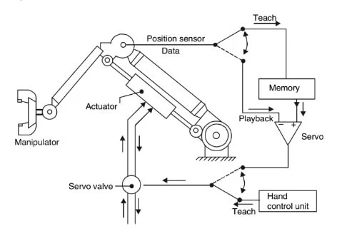
Lead-through Programming
The lead-through programming method is used with continuous-path advanced robots. In this programming method, the robot operator or the programmer physically drives the manipulator over the desired path in a sequential manner as desired to store (record) these instructions in the magnetic memory of the control unit (figure below).
When the (playback) robot is called to action, it reproduces the same sequence of moves as fed. It is very similar to digitizing in the computer numerical control machine tools. This programming method is very useful in spray painting robots.
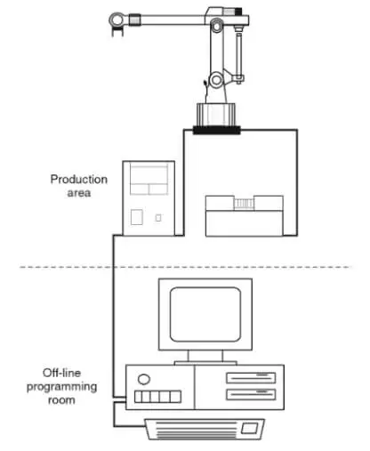
Off-line Programming
It is a programming technique that is employed where the walk-through and lead-through programming methods don’t work, that is, where the working conditions for the programmer are not conducive, such as handling radioactive billets in the nuclear reactors, manufacturing semiconductors in a clean, uncontaminated environment. In areas such as these, the only solution is telerobotics or off-line programming.
But what is offline programming? It is a programming method in which a separate computer is used to define the sequence of robotizable events without involving either the mechanical or the control unit of a robot in the programming phase.
It is similar to computer-assisted part programming (CAM) and direct numerical control, which requires complete information about the path. Since the CAD/CAM database is available, it is not a difficult task as such to teach the path to the robot.
Other databases, for instance, related to the location, geometry, and so on, are also used in this regard to define a relationship between a robot and its manufacturing environment (machine tool, cutting tool).
The path to be followed by the manipulator is simulated on the cathode-ray tube (CRT) and checked. In addition to this, a complete kinematic analysis must also be performed once the robot is ready to run the program instructions.
It requires the use of powerful yet highly sophisticated software such as GCA corporation, Cincinnati Milacron, and McDonnell Douglas Automation, among a few others.
At present, there is no telebotic language as such that exists. However, in the coming future, it is not too late for such such milestone would be achieved with great success.
On an industrial scale, the applications of off-line programming are numerous. It is used in the implementation of computer-assisted manufacturing (CIM), where the use of robots is indispensable.
One of the best merits of adopting an off-line programming methodology is to keep time from squandering in the training of robots by simulating the paths-cycles to perfection.
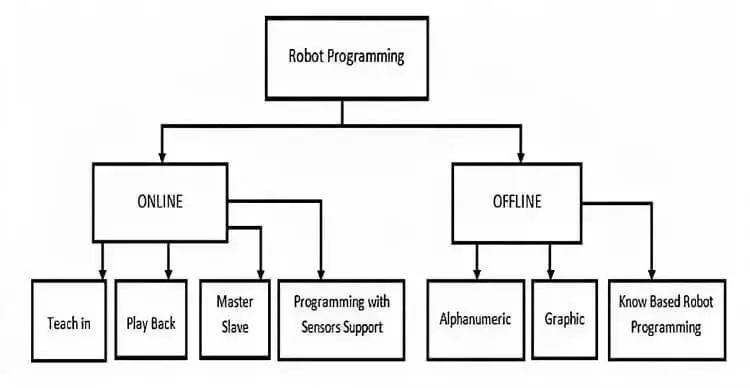
The figure below shows a comparison between online and offline methods used in programming languages.
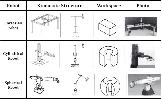
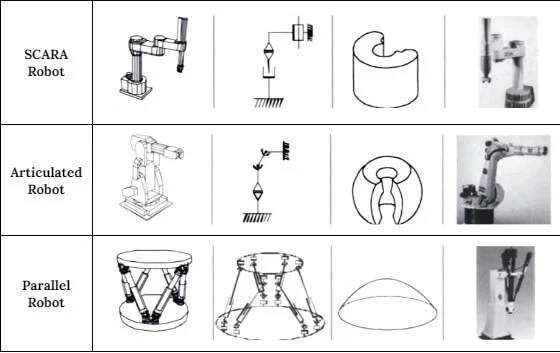
A summary tabulated below expresses various industrial robots discussed above, along with their kinematic structure, workspace, and photo.
Frequently Asked Questions
How many classifications of robots are there?
There are four classes based on which robots are categorized. These classes include degree of freedom, geometry and coordinate system, programming method, and lastly, control system.
What is the classification of robots according to the geometry and coordinate system?
Based on the geometry and coordinate system, the robots are classified as cartesian robots, cylindrical robots, polar robots, and articulated-arm robots.
How are the robots classified according to the control method?
The robots classified based on control systems include nonservo-controlled and servo-controlled robots (both point-to-point and continuous-path robots servo-controlled).
I am the author of Mechanical Mentor. Graduated in mechanical engineering from University of Engineering and Technology (UET), I currently hold a senior position in one of the largest manufacturers of home appliances in the country: Pak Elektron Limited (PEL).