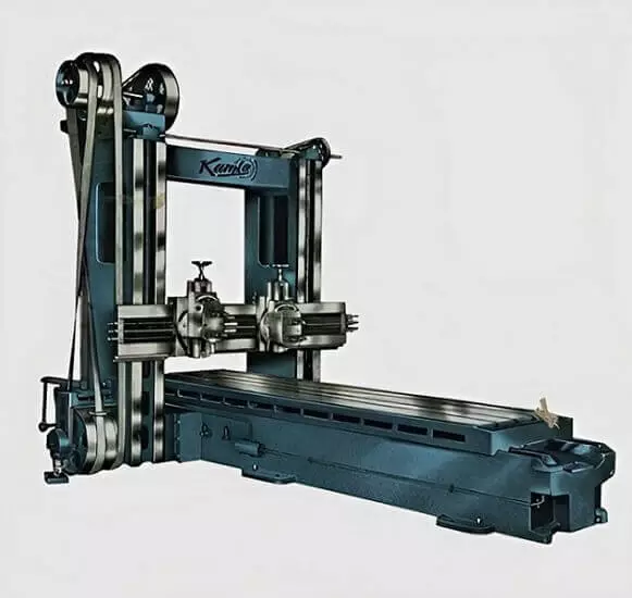
Planing machine is commonly known as a planer. It is a machine tool that is used to generate plain and flat surfaces of the work that are larger in size and heavier in weight compared with those held in the shaper.
Both planers and shapers are part and parcel of the machine tool and machining domain and have been historically used to flatten metal surfaces; however, the principal difference between the two lies in the relative motion between the worktable and the cutting tool.
In a planer, the job is held on the worktable that reciprocates past the stationary cutting tool with feed given only for lateral movement. Contrary to this, in a shaper, the cutting tool mounted in the ram reciprocates while the workpart or job is clamped on the static worktable to which is provided a cross-wise feed.
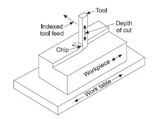
Working Principle of Planer
As shown in the figure below, the working principle of a planer is thus:
The cutting tool remains stationary while the job clamped on the worktable reciprocates past the static cutting tool during the cutting stroke of the machine.
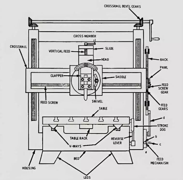
Principal Parts of Planer
Let’s discuss each part of a double housing (or column) standard planer. It is illustrated schematically in the figure below:

Bed
The bed is a boxlike casting that is ribbed crosswise. It has two v guideways at its top for the planer table that reciprocates back and forth during machine operation.
Bade is designed to support housings and miscellaneous structures. The hollow space within the box of the bed that is omitted in the diagram contains the driving mechanism of the table. It is bolted to the floor and is mounted on a flat robust foundation.
Table
It is a heavy and sturdy rectangular casting that supports the work and reciprocates back and forth on the v-guides of the bed. The table carries slots for fastening T-bolts and other devices for clamping.
Sometimes, hydraulic bumpers are fitted at the end of the bed to keep the table from overrunning.
Housings or Columns or Uprights
These are the rigid vertical structures that are placed on each side of the bed and fitted there. To accommodate jobs of different heights, the front face of the columns/housings is properly machined to provide precision ways for up and down movement of the cross-slide. In addition to that, two side-tool heads or tool posts also slide on the frontal face of the column of a planer.
Cross-rail
A cross-rail connects the two columns of a planer. At any position along the marked length of the columns, the elevating screws are provided, which when rotated, keep the cross-rail in an accurate horizontal position. In a typical planer, the cross-rail contains two tool-heads and a saddle. The tool-heads are mounted planing tools in the tool posts.
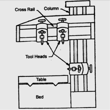
Tool Head
The toolhead of a planer, as shown is similar to a shaper in terms of construction and design. The difference lies in terms of its two sets instead of one that is provided on the cross-rail.
Types of Planers
The planers are widely categorized as follows:
- Standard or double housing planer
- Open side planer
- Pit planer
- Plate or edge planer
- Divider table planer
Standard or Double Housing Planer
It is the most common type and is the same as described above. In it, the length of the bed is twice the length of the worktable or even may exceed it. It has two columns or housings or uprights. The worktable is actuated using mechanical or hydraulic means.
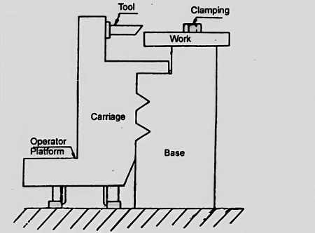
Open Side Planer
It is the second most common type that is commercially used. It consists of a column or housing provided only on one side of the bed.
The cross-rail is fastened to the column at one end, while its other end remains suspended as cantilevered. This design is supportive in handling and machining relatively large-sized parts or jobs with increased surface area.
Pit Planer
It is a massive unit and has a maverick (unique) design. In the pit type, the worktable remains stationary while the column that carries the cross-rail reciprocates back and forth on the horizontal rails that are provided on both sides of the worktable. It thus helps machining jobs larger in size with less footprint (occupies less floor area).
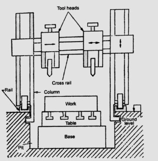
Plate or Edge Planer
It is designed differently than a typical planer. Its prime purpose is to square and bevel the edges of steel plates that are used in shipbuilding and pressure vessels.
Divided Table Planer
It carries two worktables that are arranged on the bed. Both may or may not reciprocate together. It’s solely up to the operator’s machining needs.
One of the benefits of using such a design lies in the reduction of the job set-up time: one table performs the machining work while the other remains under job set-up conditions.
Feed Mechanism
In a planer, the feed is provided to the worktable on which it is mounted the job. Feed is given to the worktable at the end of each return stroke. The cutting tool is given both the down-feed and the cross-feed.
The cross-feed is actualized for the large horizontal jobs mounted on the table. At the end of each return stroke, the tool fitted on the tool head slides slightly by a pre-determined amount, thereby giving a necessary cross-feed.
The down-feed is provided by rotating the down-feed screw mounted on the tool head in case of machining vertical or angular surfaces of the job. Feed is provided either using a friction disc or an electrical device.
Since the length of the table in a planer is quite long, the bull gear completes a great number of cycles during the forward as well as the return stroke of the table which is not the case in a shaper.
In shaper, using the friction disc the bull gear is connected to the gear train at the end of the return stroke for faster feed while during the forward stroke, the feed mechanism remains disconnected.
Work Holding Devices
Since the worktable of a planer is quite big in size as we elaborated above, it takes a lot of time for job setting. Therefore, special heed is given during the job setting process in terms of selecting proper clamping devices for entering only the needful clamping pressure, thereby avoiding the undesired strain in the job. Some of the key work-holding devices in a planer are shown below:
Standard clamping devices for holding the job in a planing machine include:
- Vices
- Step blocks
- T-bolts
- Clamps
- Jacks
- Stops
- V-blocks
- Planer centres
- Stop pins
- Toe dogs
These work-holding gadgets are similar to those used in a shaper but in the case of a planer, these devices should be heavier, sturdier, and bigger in construction.

The figure above shows work-holding devices as below:
- Bolt
- Clamp plate
- Fex clamp plate
- Stop pin
- Adjustable stop pin
- Stop pin and dogs
- Vice
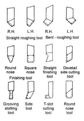
Planer Tools
The planer tools as shown schematically below are made of solid forged type or bit type using bits of high speed steel, stellite, or cemented carbide.
These are all single-point cutting tools similar to those used in a shaper. But, they have to be stronger enough to give heavy cuts during elongated cutting strokes.
Planer Operations
Planing machines are used for performing miscellaneous operations as under:
- For planing horizontal surfaces, for instance, flanged cover as shown below.

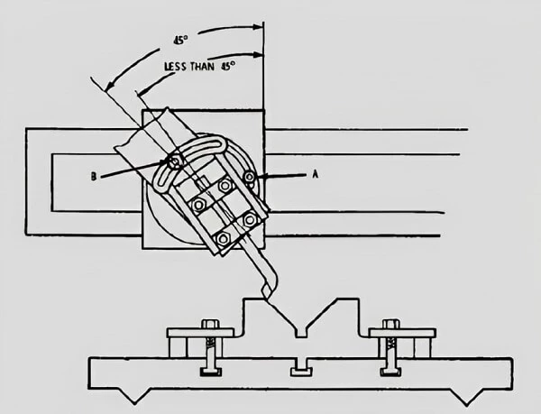
- Planing ta an angle is illustrated below schematically with the use of protractors and dial indicators as a means for measuring the angular setting of the slide head.

Likewise, the figure below shows the angular planing of the v-block.
- As shown, the figure below is the classic manifestation of the planning of the curved surface using a special fixture.

Frequently Asked Questions
Define certain terms such as cutting speed, feed, and the depth of cut for a planer?
Cutting speed: It is the rate in m/min at which the metal is removed from the job surface during the forward cutting stroke of the table.
Feed: Expressed in mm/double stroke, the feed shows the distance traversed by the tool head at the start of each cutting stroke.
Depth of cut: Given in mm, it shows the measured thickness of the metal-job removed in one cut.
How can the quicker return of the planer worktable be achieved?
Being an idle stroke, the return stroke of a planer is faster than its cutting stroke. There are several means which can help achieve the quicker return of the planer table. Some of them include the following:
DC reversible motor
Fast and loose pulley system
Hydraulic drive system
I am the author of Mechanical Mentor. Graduated in mechanical engineering from University of Engineering and Technology (UET), I currently hold a senior position in one of the largest manufacturers of home appliances in the country: Pak Elektron Limited (PEL).