
Like lathe, milling, and drill machines, shaper is also a metal subtraction machine tool. It is a historical machine whose landmark design has evolved over a while. It is inevitably available in every machine shop almost everywhere in the world.
What is a Shaper?
It is also known as simply a shaper that is used to machine flat surfaces, be they horizontal, vertical, or inclined, by using a tool that moves in a reciprocating manner.
However, it can machine parts with irregular, odd, or uneven surfaces yet made of straight-line elements. There is again an exception here: special shapers can generate contour surfaces as well.
The set-up time of the shaper machine is much lower with most of the jobs compared with other metal cutting machines.
Fixtures complex in design is replaced by simple workholding gadgets such as a vice to clamp small-size workparts.
Moreover, against planers, shapers are less expensive, versatile in operations, occupy less floor space, and consume relatively less power.
However, due to the limited stroke length of the ram, the use of a shaper machine is restricted to smaller jobs only.
Another blind-spot of shaper is its slow working, due to which it is mostly used for unit or batch production rather than for mass production.
Besides its low operations, it can produce a variety of finished surfaces with single-point cutting tools compared with multi-point cutting tools used in mills.
Working Principle of a Shaper
The working principle of a shaper is briefly described below.
- The job or the workpart or simply the work remains stationary while the cutting tool moves in a to and fro manner.
- The work is clamped on the table, and the shaping tool is fixed on the reciprocating ram.
- The table to which the work is mounted remains at a right angle to the shaping tool during each stroke of the ram. The table is given an automatic feed that is perpendicular to the ram movement.
- The cutting stroke is only the forward stroke of the ram except in the case of a draw-cut shaper, in which the backward stroke is also a cutting stroke.
- The backward stroke of the shaper that does not perform the cutting operation is also called an idle stroke.
- An indexed feed can also be given to the workpart against the cutting tool in the horizontal and vertical directions.
Construction of a Shaper
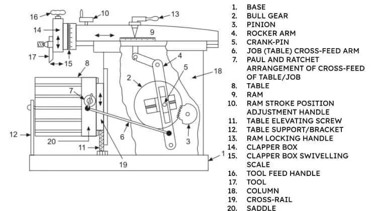
The principal parts of the common shaper machine are briefly described below:
- Base: Made of cast-iron, it is used to bear the entire weight of the shaper as well as to dampen the vibrations caused by cutting forces exerted by the tool on the work.
- Column: It is a box over the base that carries the ram-driving mechanism. It provides two horizontal machined guideways (P) at its top, over which the ram structure is mounted and can slide in a reciprocating fashion. It also provides two more vertical guideways (J) for the Crossrail block. Structurally, it consists of two column walls that are mounted on the base. It houses a quick return mechanism of the RAM, speed-reducing devices, as well as a RAM stroke controlling system.

- Ramp: It is mounted upon the column guideways and is a reciprocating mechanical member. It carries a tool-slide as well as a mechanism for adjusting the stroke length.
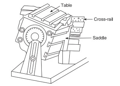
- Crossrail: The cross-rail assembly consists of a cross-rail, cross-feed screw, table, and table brackets. It is fitted on the front two vertical-guideways (J) of the column. Or, more simply and precisely, it is provided with two guideways in the vertical place to the ram axis. The cross-rail is also provided with two cross-rail guideways (K) in the vertical plane. The worktable can be lowered and elevated by rotating the elevating screw (D) to accommodate different sizes of the work, which in turn makes the cross-rail slide up and down along the vertical guideways (J). The worktable is secured to the cross-rail apron which slides on the horizontal ways on the cross-rails. The cross-feed screw (N) engaged in a mating nut, is secured to the back of the apron. It can be turned either manually or electrically powered to slide the table horizontally on the guideways (K).
- Saddle: It is labeled C in the diagram. It is connected to the table. When the cross-feed screw (N) is operated, it makes saddle C, and thus, the table feed in either direction on the guideways (K).
- Table: Made of cast iron, it is rectangular in geometry. It carries slots for holding the work. It can be moved upwards, downwards, and sidewards using the elevating screw (D) and feed-screws (N). The cross-feed is given to the table by the Paul and Ratchet arrangement. The worktable can be plain or universal. The universal type, as shown in the figure, can be swiveled right or left. While other configurations of the table can be tilted fore and aft at a small angle to the ram. It has T-slots cut on top and sides for clamping the work.

- Toolhead/Shaperhead Assembly: It is provided at the front end of the ram. It can swivel along any angular direction to shape the angular surfaces.
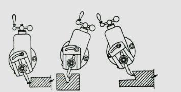
The toolhead assembly consists of a tool slide (E), clapper block (D), a downward feed mechanism or a feed screw (I), and a tool post (G), among many others, as shown in the figure below. For downward cutting other than straight, the clapper box is swiveled right or left.
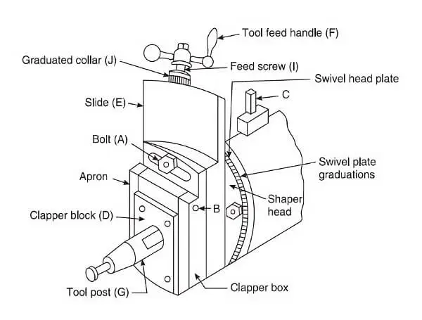
The tool is fixed in the toolpost (G), and its movement is controlled by the tool feed handle (F), which, when operated, allows the tool-slide (E) to move up and downwards. The depth of cut is provided by the feed screw (I) that has the graduated collar (J) for accurate adjustment.
The clapper block (D) is attached to the tool post (G) via pin (B).
When the ram moves in the forward direction as a cutting stroke, the clapper block finds a rigid support at its back due to the presence of the clapper wall. However, during the return or idle stroke, the clapper block slides forward, thus allowing the tool to touch the work surface without scratching.
Shaper Cutting Tools
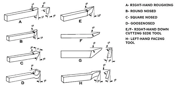
Cutting tools that are used on the shaper are either straight or bent cutting tools. They are shown in the figure below with their respective CLEARANCE ANGLES of cut. The most common types include roughing, finishing, side-roughing, and side-finishing tools.
However, special cutting tools perform special operations such as cutting T-slots. It should be noted that the clearance angle is shorter in the case of the shaper cutting tools compared with the lathe tools because, in the case of shaping machines, the tool remains perpendicular to the plane of the work. Moreover, its length is also shorter compared with its lathe counterpart.
Types of a Shaping Machine
There are several ways in which the shapers can be grouped. Some of them are discussed below:
According to the position of the ram
- Horizontal-type Shaper: in the horizontal type, the ram moves in a horizontal direction parallel to the earth’s surface. It is used to flatten surfaces.
- Vertical-type Shaper: It is specifically called a slotter. Its ram moves in a vertical direction. Its table is with rotary setting and is driven by a crank hydraulic or screw. It is precisely used for cutting slots and shaping keyways.
- Traveling-head type Shaper: The ram, during its reciprocating motion, moves cross-wise, thus giving a required feed. The ram is mounted on a saddle that slides sideways. Heavy workpart is held static on the basement of the machine while ram provides the required feed-movements to the tool as well as the workpart.
According to the ram movement mechanism
- Crank-type Shaper: It is the most widely used shaper. The rotary motion of the bull gear is converted into the reciprocating movement of the ram.
- Hydraulic-type Shaper: Instead of a crank mechanism, the reciprocating movement of the ramp is provided by hydraulic power. It provides constant RAM speed from the beginning to the end. It gives flexibility in terms of speed and feed control. It is eliminative of the shock-energy and slows down when the cutting tool gets overloaded. It gives noise-free operation.
- Geared-type Shaper: It is found rare in workshops. It makes use of a rack below the ram and is entangled with a pinion that is driven by a gear train and motor.
According to the table design
- Standard-type Shaper: it is also called a plain shaper. It is lighter in weight and is provided with two table movements, horizontal and vertical, to give the feed.
- Universal-type Shaper: in the universal, the worktable is provided with a table bracket at the front for adjusting the height of the table according to need. Doing so permits the table to be fed cross-wise, too. The table can rotate a full circle about the saddle. It is shown below.
According to the nature of the cutting stroke
- Push-type Shaper: It provides a forward stroke as the cutting stroke only. The backward stroke is the idle stroke. The length of the ram stroke may be as long as 900 mm.
- Draw-type Shaper: Its cutting stroke is the backward stroke. It is sturdier in design and damps shocks and vibrations. The ram stroke length may go up 1800mm.
Work-holding in Shapers: Methods and Precautions
- The job smaller in size is fixed on the table using either vice or the chuck.
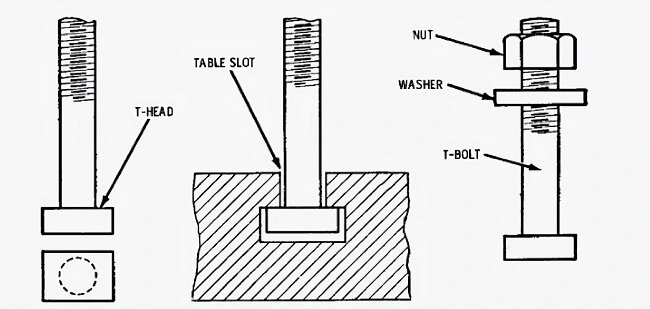
- The workpart larger in size can be held in place by using T-bolts as shown in the figure below. This is the way the workpart is mounted directly on the table of the shaper using T-bolts whose assembly parts consist of a bolt, nut, and a washer.
- The job with intricate geometry or surfaces is held using the clamps that are fastened with the table using bolt assembly and fulcrum block. The bolts should be tightened in the slots where their distance is shortest with the work yet largest with the fulcrum block keeping in view the lever principle.
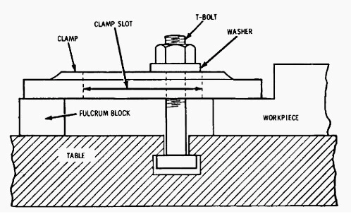
- The sequence of tightening the clamp bolts, as shown in the figure below, is necessary to distribute the clamping stresses evenly to make their net effect minimal.
- Lastly, the height of the fulcrum block should be the same as that of the work to avoid strain on the clamp bolt.
Operations Performed by a Shaper
Some of the important operations performed by a shaper are mentioned below.
- Shaper to cut flat surfaces

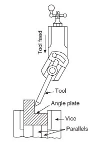
- Shaper to machine angle plate.
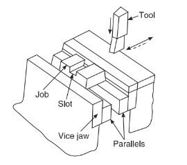
- Setting a job while cutting a slot in the work.
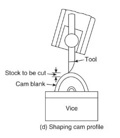
- Shaper for shaping cam profile.
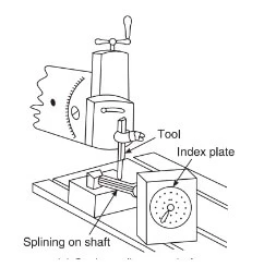
- Shaper to cut splines on a shaft.
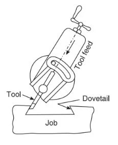
- Shaper to cut a dovetail.
I am the author of Mechanical Mentor. Graduated in mechanical engineering from University of Engineering and Technology (UET), I currently hold a senior position in one of the largest manufacturers of home appliances in the country: Pak Elektron Limited (PEL).