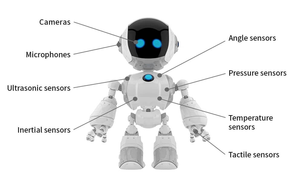
Similar to our sense organs, industrial robots do require sensors to perform the programmed tasks correctly and efficiently. They take input from the environment they operate in or from within to feed the control unit.
For example, for a cartesian manipulator or a robot arm, sensors would be required to ascertain the location to be reached or to detect any hurdle on the adopted path to do the designated task effectively and flawlessly.
Thus, a robot gathers data about itself and its immediate environment and sends this data in the form of feedback signals to the robot control system to take appropriate action thereupon. Without sensors, the structural coherence of a robot system would be simply out of joint.
Types of Robot Sensors
Sensors are one of the main components of any industrial or domestic robot. Generally, the robot sensors, based on the data acquired, are categorized as internal and external types.
Internal sensors belong to the family of those that gather the internal data or parameters of the robot, such as force, torque, direction, velocity, power level, and so forth.
Whereas, the external sensors belong to the class of sensors that collect the data outside the robot or the data about the objects or conditions extrinsic to the robot.
Both of these types shall be discussed in detail hereunder.
Internal Sensors
Robot internal sensors are integrated into the body or the structure of a robot and give feedback signals to the controller related to the inner workings of a robot. They mainly include position, velocity, and acceleration sensors.
Position Sensors
They are the sensors that are used to measure the linear and angular displacement.
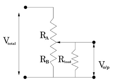
Potentiometer
It is a position sensor that generates voltage as a form of output across the resistor corresponding to the change in the position.
Precisely, it consists of a wiper or a sliding contact on the variable resistor. As the position changes, the location of the wiper on the potentiometer also changes, based on which effective resistance also changes.
Encoder
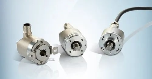
It is an optical sensor that generates or encodes a digital code that corresponds to a small change in position.
By counting a single bit or decoding a set of bits, the pulses are convertible into absolute and incremental measurements. It is because of this that the encoders are known as absolute or incremental types.
Its construction consists of a strip or a disc divided into numerous smaller sections, one being transparent and the other being opaque, arranged repetitively throughout with a source of light such as an LED placed on one side of the strip. The figure below shows an incremental encoder.
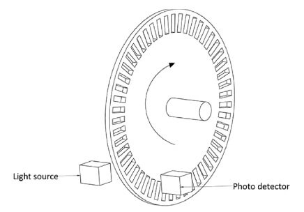
A beam of light is allowed to pass through the encoder from one side, whereas it is received or sensed by the photosensor or phototransistor on the other.
If the position of the strip is such that the light passes through its transparent section and finally gets detected by the photosensor, it generates a high signal by tuning the sensor on.
Whereas, in the case of the opaque section facing the sensor, the sensor generates a low signal and remains operationally off
Whereas, in the case of absolute encoding, the encoder’s disc/strip consists of unique pairs of transparent/opaque sections, thus generating or encoding unique codes corresponding to that position where that pair is located, thereby eliminating the need for a starting/reference point.
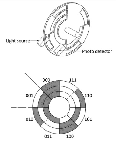
Hence, the difference between the two is given by the way they communicate information related to the position.
Absolute encoders give unique and fixed position values against each transparent/opaque pair on the encoding disc or strip. In contrast, incremental encoders give the position value by counting pulses relative to a reference point.
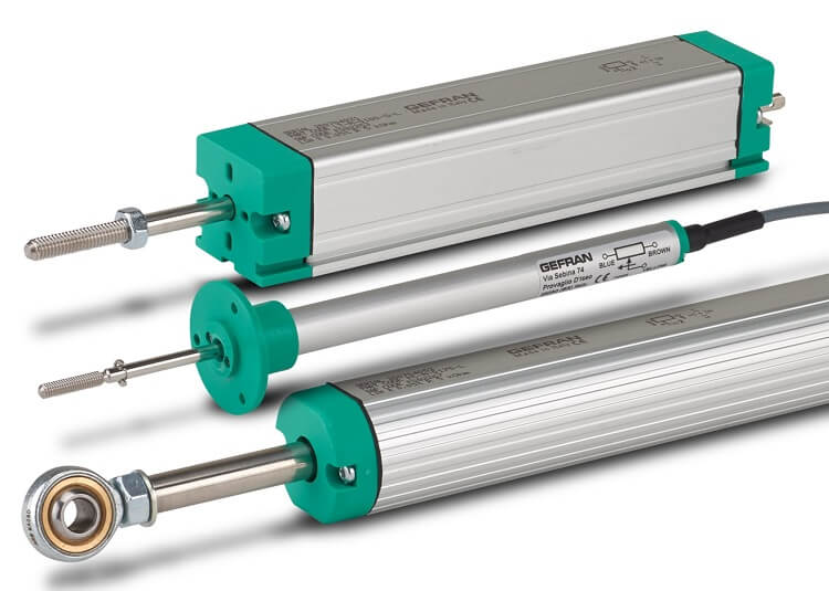
LVDT
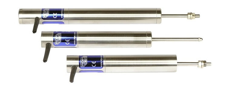
It is an acronym for linear variable differential transformers. It is a position sensor that generates an analog output voltage proportional to the displacement, which in turn is proportional to the movement of the core.
A transformer is regarded as an electric-to-electric energy converter that changes voltage to current ratio, keeping the energy input and output the same.
The voltage steps up or steps down based on the number of turns of the transformer. Subsequently, current varies inversely to the number of turns of a transformer.
When a current passes through one coil due to an electric flux, a voltage is induced in the nearby secondary coil based on its number of windings.
Current, however, decreases proportionally in the secondary coil. This is how an LVDT gives an accurate measure of the displacement.
The figure shown below depicts the working principle of LVDT. An iron core moving to and fro generates AC signals with a voltage amplitude proportional to the displacement of the core, which is surrounded by two secondary and one primary coil.
As a result of core displacement, the magnetic field between the primary and secondary coil changes, due to which variation in voltage amplitude occurs in the secondary coil, which is a linear function of the core displacement as shown graphically.
Thus, the output voltage of an LVDT varies linearly and proportionally to the input position of the iron core.

Velocity Sensors
The measurement of change in position in a fixed time interval calculates velocity. Hence, all position sensors can also be used for determining velocity.
In the case of encoders, the pulses generated per unit time give the measure of velocity. Two types of velocity sensors are explained below.
Tachometer
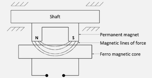
It is used to measure the rotations of a rotating element in a unit of time. Its working principle is governed by Fleming’s rule, which states the voltage produced varies directly proportional to the magnetic flux linkage.
As shown in the figure below, as the shaft rotates in the magnetic field of the permanent magnet, a voltage is induced in the ferromagnetic coil, which is proportional to the rotational speed of the shaft.
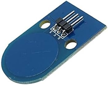
Half Effect Sensor
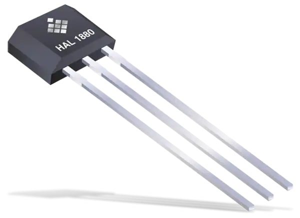
These sensors are based on the Hall effect, named after Edward H Hall in 1879. According to this rule, a voltage is induced in the Hall element, which varies proportional to the magnetic field.
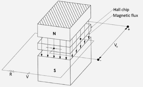
The output voltage is analog, which is converted to the digital signal for applications that require digital processing.
As shown, a voltage is applied on the opposite sides of a Hall chip. If the magnetic field in a direction orthogonal to its surface is zero, no voltage is produced, and vice versa.
Or, when a shaft rotates, the corresponding magnet also rotates, which induces a voltage in the Hall chip proportional to the magnetic field induced, thereby detecting the proximity of the shaft as well as its rpms.
Acceleration Sensors
These sensors have rare use in robotics. The position sensors used for velocity measurement may also be used for acceleration measurement by dividing the measured velocity per unit time.
Moreover, mathematically, acceleration is defined thus:
\alpha=\frac Fm
Where F is the force which is measured using force sensors such as a strain gauge. Using this formula to calculate acceleration imposes an excessive load on the processor, thereby making this method of measuring acceleration very rare.
External Sensors
As their name implies, these are the sensors that interact with the environment or the surroundings, which contain the objects that robots have to handle as per a programmed set of instructions.
They may include touch sensors, proximity sensors, force/torque sensors, vision sensors, and many others.
They are typically of two types: contact and non-contact sensors. Let’s discuss some of them in detail.
Contact Sensor
Contact sensors are those that operate by being in contact with the objects retained in the surroundings of a robot to collect needful data.
Some of its examples are touch or tactile sensors, while others may include force or torque sensors that operate as a result of contact with the object sensed.
Force Sensor
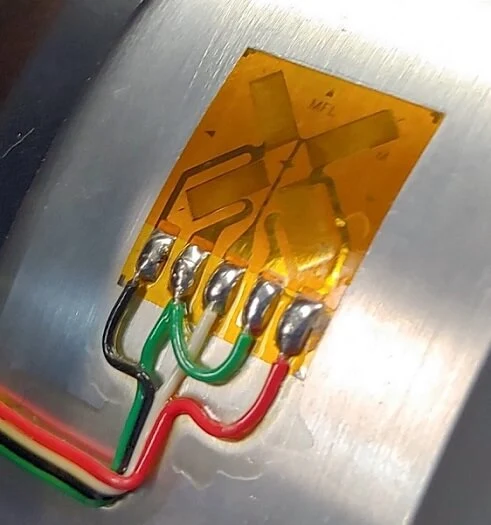
These are the sensors that sense the force applied or experienced. The strain gauge is the most common type that senses and calculates the force applied at the end effector or the wrist of a robot arm, as well as the loads on the links and joints of a manipulator.
In its construction, it consists of a conducting material of a fine-wire cemented on an insulating material called a wafer as a base. It is in this base or wafer where the strains are measured.
Its working principle is simple: when the force is applied on a fine wire that compresses or stretches it, its length changes as a result, which in turn changes the resistance of that wire (both length and resistance of a wire are directly proportional to each other).
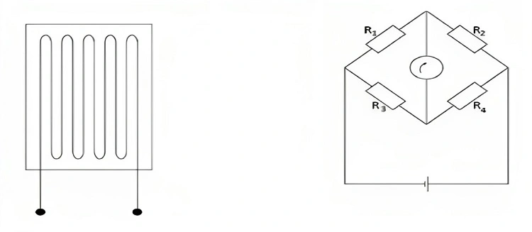
By measuring the net resistance, one measures the net force experienced. The typical resistance of a strain gauge ranges from 100 to 500 ohms. Usually, a Wheatstone bridge arrangement is used with the strain gauge to calculate the net resistance of the wire.
Likewise, the force can also be calculated using sensors made of special materials called piezoelectric materials. These are the materials that develop an electric potential difference on the surface when a force is applied to it.
Made of symmetrical, elastic materials, they give the measure of the force applied by measuring the deformation in the piezoelectric materials. This phenomenon is called the piezoelectric effect. It is reversible.
Touch Sensor
They identify the presence or absence of an object by touching it. In the domain of a robot, a touch sensor takes the form of a gripper with microswitches that turn ON and OFF depending on the presence or the absence of the sensed object.
Apart from microswitches, which are abundantly used in robots, pressure-sensitive piezoelectric sensors are also employed to identify the presence/absence of an object by generating an electric current when it is subject to external force.
Its latest form is a tactile sensor, which is arranged in the form of an array of touch sensors to give additional information regarding the shape, size, or material of the object to be identified.
In its construction, a touch sensor is made of an LED source, a plunger, and a detector. When the plunger moves or displaces, the light coming from the LED source is diverted, which is sensed by the light sensor on the opposite side. This light sensor gives output based on the displacement of the object.
Non-contact Sensor
These are the sensors that do not come in contact with the robot’s environment. For example, they are typically designed to measure the distance of the sensed object with the robotic arm. They may include ultrasonic sensors, proximity sensors, optical sensors, and others.
Let’s discuss a few of them in a bit of detail.
Ultrasonic Sensor
These are the most common types of non-contact-sensor categories. They measure the distance of an object by transmitting ultrasonic sound waves and then analyzing the reflected waves via the reflected signals.
They are chiefly used to detect the presence of an obstacle in the way. They are simple in construction and not much costlier.
Technically speaking, they work to measure distance using the time-of-flight technique.
A transducer emits a pulse of high-frequency ultrasound wave, which, when reflected through an obstacle on its bath, gets received by the receiver, thereby covering twice the distance between the transducer and the object.
It is now equated to the product of the time elapsed and the speed of the sound to calculate the actual distance.
Proximity Sensor
It is used to identify how close or farther an object is for another (for example, a gripper in the case of a robot).
They are of various types and include magnetic, eddy current, Hall effect, inductive, optical, and capacitive proximity sensors, among many others.
The prime purpose is to identify how far an object or a workpiece is from the robot’s gripper or if there is a huddle anyway.
Metal surfaces are commonly detected using inductive proximity sensors. Whereas, non-metal surfaces such as wood and plastics are detected using capacitive proximity sensors.
Range proximity sensors give a direct measure of the distance of an object from the sensor.
Similarly, the proximity sensors used to sense the presence of a human being within a work cell are equipped with various technologies based on electric, magnetic, optical, acoustic, or infrared devices.
Optical sensors work by sending visible light or IR radiation to the targeted object to detect its proximity to the sensor.
Let’s discuss a few of them in a bit of detail.
Optical Sensor
They are broadly categorized into quantum and thermal optical sensors. The quantum optical sensors are based on quantum effects such as photoconductive effects. In comparison, the thermal optical sensors operating in the IR range work effectively in far away IR regions. They are further of two types: the active far infrared sensors (AFIR) and the passive infrared sensor (PIR).
The most typical optical sensors include photoconductive sensors, photodiodes, and phototransistors. All these sensors measure the distance directly by measuring the power of the light that they absorb.
They are multipurpose sensors used in sensing position and measuring distance, temperature, variation color, and quality control, among many others.
In their basic working principle, the photons are absorbed by a semiconductor, which in turn increases the energy of the electrons and, thus, their current flow, which is measurable without any difficulty.
The increase in the electric current varies directly proportional to the intensity of photons falling on the semiconductor. The sensors based on this working principle are called photo-conducting sensors. They are made of materials according to the range of light employed: typical materials include cadmium sulfide, cadmium selenide, lead sulfide, and others. It is shown below.
Photodiodes, on the other hand, work as optical sensors by absorbing the photons being incident on them and thereby generating the proportional electric current.
They work in the reverse bias mode. In that mode, a small current called a dark current flows through a diode. When photons strike it, the current flow increases proportionally.
Phototransistors, on the other hand, do not have the base region like in a typical transistor. Rather, it is replaced by a light-sensitive base region.
When there is no light, such as at night, the collector current is zero. However, when daytime photons strike the sensor, the collector current increases proportionally with the intensity of the photons striking it.
PIR
They are passive infrared sensors that work by detecting the infrared waves radiated by the object.
These waves upon absorption by the sensor, generate the corresponding output voltage. In the case of lower frequencies (larger wavelengths), thermal effects become more prominent, which means that the temperature of the absorbent surface increases, which is measurable.
Pneumatic Sensor
It operates with compressed air. It is equipped with an inlet port to which a low air pressure is applied. In front of the sensor, the outlet port is used to escape or release the air pressure.
In the presence of an object facing the outlet port, the pressure at the outlet port increases thereby giving an account for the proximity of a nearby object.
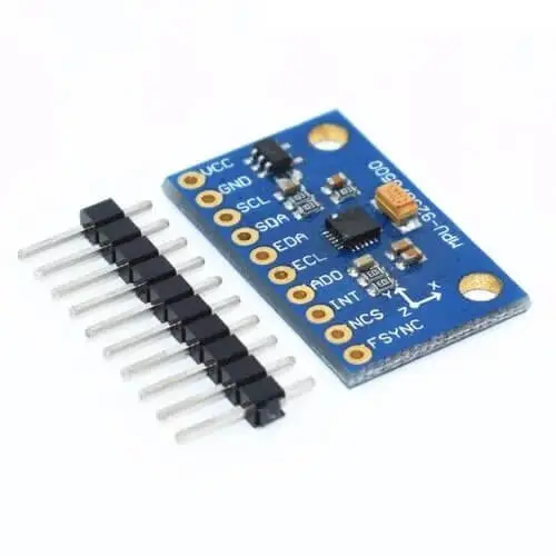
Mems-based Sensors
Microelectromechanical systems (MEMs) sensors are extensively used in robots today. Due to their very small size, fair economy, and great sensing precision, they have occupied a prestige marketplace in a short time.
Just like other sensors, in MEMS-based sensors, a parameter is sensed using an electric response from the sensor.
They use microscale mechanical components that are integrated into an electronic circuitry to sense and measure the desired phenomena.
The most common techniques that MEMS-specific sensors use are piezoelectric sensing, capacitive sensing, and optical sensing techniques.
They include MEMs pressure gauge, MEMs pressure sensor, MEMs strain gauge, and MEMs accelerometer, among many others.
What are the chief characteristics of a robot sensor?
There are certain characteristics of the sensors based on which they are selected for a particular application. Some of the main characteristics are mentioned below:
Reliability
It is the ratio of the number of times a sensor works properly to the total number of times it is subject to use. The more reliable a sensor is, the higher its credibility for a satisfactory and continuous operation.
Accuracy
The accuracy of a sensor is the measure of the difference between the measured value and the actual value. The higher the accuracy of a sensor is, the closer is the measured value to the actual value.
For example, if a position sensor has 0.01mm accuracy, it signifies that the maximum variation between the measured and actual values is 0.01mm.
Repeatability
If a sensor reads the same measurement again and again, the difference between these readings is known as repeatability.
It is not always true that a highly repeatable sensor is equally accurate as well. The difference between accuracy and repeatability is explained well in the diagram below.
Moreover, it is important to note that repeatability is a more crucial aspect of a sensor than accuracy.
Cost
It is the price in dollars. Among many others, it is also a critical factor in deciding a suitable sensor for a specific application.
Size and Weight
They are important considerations as well due to space constraints (say, within robot joints) and the limited load-carrying capacity of a manipulator.
Range
It gives the measure of the difference between the highest and the smallest input or output values required to maintain the level of accuracy of a robot.
Response Time
It is the time taken by a sensor to respond to a change in input value. More precisely, by response time, one means the time required for the output of a sensor to reach, for instance, 95% of the total change. In most of the cases, it must match the response time of the system.
Resolution
It is the minimum step size measurable by a sensor. The higher the resolution of a position sensor, the more likely it is that it can measure up to very small variations in the position.
In the case of an absolute encoder, if there are n bits available, it can measure up to 2n levels. For example, for a four-bit encoder, the resolution would be 3600/16 or 22.50.
Form of Output
There are several forms of sensor output: voltage, current, mechanical movement, and so on. Sometimes, the output is converted from one form to another, say, in the case of the strain gauges or LVDT.
Interfacing
The output signal of a sensor must be readily interfaceable with the standard plugs or needful equipment for subsequent action.
Linearity
It is the characteristic of a sensor due to which its output varies proportionally with the input (albeit for a range of values). In practice, all the sensors are nonlinear devices due to the existence of a nonlinear relationship between the sensor’s input and output.
Sensitivity
It is a crucial aspect of any sensor. It gives the measure of how well the output of the sensor responds to the input.
If a sensor has higher sensitivity, it implies that it would respond promptly with even the slightest change in the input.
Mathematically, it is defined as the ratio of the change in the output to the change in the input that triggered the output change.
Applications of a Robot Sensor
As explicitly stated above in detail, robot sensors receive input data and communicate it to the control unit for an appropriate response. The areas of application of these sensors are widespread, from hazard monitoring to quality control and ensuring interlocks for work and so forth.
- In the case of safety and hazard monitoring in sophisticated (automated) workspaces, sensors are of fundamental importance to keep the robot as well as the working person from accident or any serious injury.
- When it comes to implementing interlocks for the control of work cells, sensors play a critical role. Interlocks are primarily used for coordinating a sequence of various activities related to an equipment’s internal assembly in a work cell. In this regard, sensors play a pivotal role in the correct interlocking of the different pieces of equipment in a work cell.
- Lastly, in the domain of quality control (QC), sensors automatically monitor the part quality by ensuring certain quality checks, for example, weight, size, tolerance, and so on, by using different types of sensors.
Frequently Asked Questions
How are sensors classified in robotics?
They are mainly classified as internal and external sensors: internal sensors measure the changes intrinsic to the robot body and include position sensors, velocity sensors, and acceleration sensors, whereas the external sensors receive data from the immediate surroundings of a robot and include touch sensors, proximity sensors, ultrasonic sensors, optical sensors, PIR and others.
What are the advantages of a robot sensor?
Using sensors in robots gives multi-axial advantages on an industrial scale: they provide environment-specific information to the robot, including the manipulator (robot) itself. It helps in object recognition. It assists in improving productivity by carrying out operations more safely, efficiently, and autonomously.
What are the general characteristics of a robot sensor?
The characteristics of a robot sensor are the same as that of an ordinary sensor. They include reliability, repeatability, sensitivity, range, size, linearity, response time, resolution, interfacing, and others.
I am the author of Mechanical Mentor. Graduated in mechanical engineering from University of Engineering and Technology (UET), I currently hold a senior position in one of the largest manufacturers of home appliances in the country: Pak Elektron Limited (PEL).