
CAD and CAM are two computer-aided tech tools used for product development and manufacturing. In the CNC machining framework, they both work together to automate part design and production. The current article is solely dedicated to discussing their robust integration in a simplified manner.
CAD/CAM?
CAD stands for computer-aided design. It refers to any software that is capable of defining as well as editing, and modifying a mechanical component in terms of its geometry, surfaces, and solid models.
Whereas CAM stands for computer-aided manufacturing. It refers to the mediation of computer technology and special software/applications for the automation of the machining of realtime objects or industrial parts using 2D drawings or 3D solid models produced by CAD software.
Integration of CAD and CAM
The robust integration of CAD and CAM does the following: it provides the necessary link between the software systems that helps streamline the transfer of files between important functions such as design modeling, manufacturing modeling as well and numerical control (NC) programming.
The sole purpose behind the powerful collaboration between CAD and CAM files is to provide a robust link based on software that merges the software necessary for part design to the machine intended for fabricating that part.
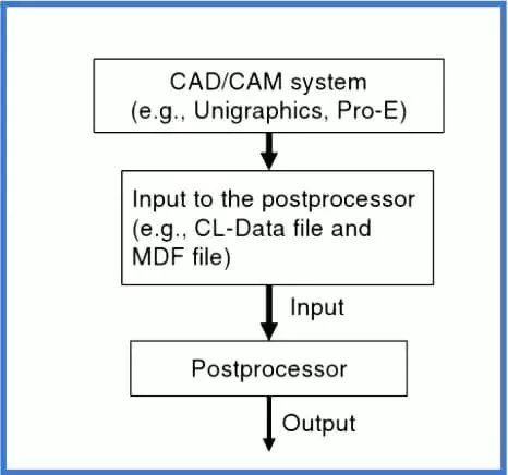
As shown below, the integration of the CAD and CAM process flow begins with the creation of 3D-CAD models by the part-designer or the product engineer, which are then converted to the machine G codes and finally end in part fabrication.
There are no universal NC codes that the different NC controllers from different manufacturers interpret. Therefore, a postprocessor is used to translate the actions taken in the CAM software into machine codes. The most commonly used CAM software is Delcam.
The CAM program is specific in its task: it outputs cutter location (CL) data files, which specify tool paths as well as unique yet critical operations. This CL data format is machine-independent. The role of the postprocessor is imminently crucial here as it translates the CL data into actionable G (as well as M) codes, which are used to control the machining operations in a real-time world.
More precisely, the postprocessor not only writes a machine-specific command program based on G and M codes it also sends this program to the CNC machine for immediate execution. If the postprocessor is good enough, one is away from the headache of cumbersome editing of the G codes. Therefore, it is urged to choose a system with smart postprocessing capabilities.
The functions of a postprocessor can be summarized as thus:
- It converts the tool position in the part coordinate system to the machine coordinate system.
- It processes linear and circular interpolations, among others.
- It generates the correct spindle speed, feed rate, tool to be used, and other machine-operation-related codes.
- It verifies the correctness of the tool/path travel range.
- It modifies and creates commands used to allow for requirements of the NC machine controller.
- It gives output in a format compatible with the NC machine.
It is noteworthy that when the machining operations are so simple, there is no need for the use of CAM software for generating programs or CL data files. In that case, using 2D drawings or 3D solid models made in CAD, the CNC machine operator writes the NC program based on G&M codes, which specify tool movement, tool path, cutting parameters, and others without taking help from the CAM software. Now, the CNC machine reads and executes the NC program by acting upon the stated instructions.
Step-by-Step Computer-aided CNC Processing
The flow of computer-aided CNC processing can be summarised thus:
- Using CAD, develop a 3D solid model of the part.
- Decide the required machining operations and cutter path directions.
- Select the required tooling.
- Run the CAM software program to generate the CNC part program based on G and M codes, as well as setup sheets and a list of tools. Postprocessor, being the critical component of the CAM software would translate the tool path and required machining instructions into a format compatible with the CNC machine control system.
- This CNC part program may be verified and edited using a virtual machine simulator such as CNCez.
- Download the CAM-made CNC program to the CNC machine for part fabrication.
- Verify the program on the actual machine once again, and correct it if necessary.
- Finally, run the program and start CNC part machining.
How to read an NC Block?
An NC program is generated by the manual input of the G-codes to control tool movement. Whereas, a CNC program is a sophisticated form of an NC program in which computers are used to generate machine programs that specify cutter location, tool path, tool movement, and others (by using CAM software such as Delcam, ProE, and others).
In either case, the output in the form of a G and M code program consists of sentences called blocks. Each block consists of a sentence written on a separate line. These blocks may range from hundreds to thousands in an NC or CNC program. They are arranged in a particular sequential manner to ensure safety, predictability, and readability.
Again, the block is defined to have consisted of a group of NC/CNC words terminated by the end-of-block character which is usually carriage return or CR.
In a block, there is an alphabet address code, for example, G, M, F, and others as tabulated below. It follows a numeric, integer, or floating point.
Frequently Used Address Codes
| S# | Code | Function |
|---|---|---|
| 1 | D | Tool Diameter Selection |
| 2 | F | Feed rate assignment |
| 3 | G | Preparatory Function |
| 4 | H | Height off-set register number |
| 5 | I | X-axis incremental location of the arc center |
| 6 | J | X-axis incremental location of the arc centre |
| 7 | K | X-axis incremental location of the arc center |
| 8 | L | Loop count |
| 9 | M | Miscellaneous Function |
| 10 | N | Block number |
| 11 | O | Program name |
| 12 | P | Dwell time, scaling |
| 13 | R | Retract distance when used with G81-83, Radius when used with G02,03 |
| 14 | T | For Tool selection |
| 15 | X | Y-axis incremental location of the arc center |
| 16 | Y | Y axis coordinate |
| 17 | Z | Z axis coordinate |
Sample NC block
For a better understanding, consider a sample-block written below:
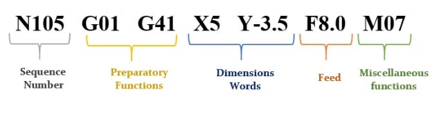
According to the above block instructions, the cutter would perform a cut from the current cutter position to X= 5.0 in and Y= -3.5 in along a straight line at a feed rate of 8.0 in/min.
Precisely, the above sample block consists of seven NC words, which are described below:
- N105 shows the sequence number of the block.
- G01 is an NC word that specifies the linear motion of the cutter.
- G41 expresses the cutter radius compensation from the left.
- X5 is the next cutter location along the X-axis
- Y-3.5 is the next cutter location along the y-axis.
- F8.0 is for the feedrate.
- M07 is a miscellaneous function for turning the coolant on.
More strictly, the X and Y commands refer to the cutter location, that is, the center point of a bottom-faced end mill or the tip of a drill bit. Finally, the data on cutter location defines the tool path either along a straight line (G01) or by circular arcs (G02/03).
Likewise, all the other NC blocks are readable. In this terrain, the G and M codes will be described in the following articles for their proper understanding.
Frequently Asked Questions
What is CAD?
CAD is an acronym for computer-aided design. It refers to any software that is capable of defining as well as editing, and modifying a mechanical component in terms of its geometry, surfaces, and solid models.
What is CAM?
CAM stands for computer-aided manufacturing. It corresponds to the mediation of computer technology and special software/applications for the automation of the machining of realtime objects or industrial parts using 2D drawings or 3D solid models produced by CAD software.
How are CAD and CAM software integrated?
2D drawings or 3D solid models of a part or sub-assemblies are created using CAD software such as AutoCAD. These 3D models (or 2D drawings of the 3D models) are then fed to the CAM software such as Delcam, which generates an NC program based on G codes that specify cutting tool path, tool movement, and others. This program is now executed in the CNC machine for machining desired part geometry.
I am the author of Mechanical Mentor. Graduated in mechanical engineering from University of Engineering and Technology (UET), I currently hold a senior position in one of the largest manufacturers of home appliances in the country: Pak Elektron Limited (PEL).