A machine tool or simply a machine that is used to perform machining processes or operations on a rotating piece of metal (or workpiece) is called lathe machine or simply a lathe. These machining operations include turning, facing, drilling, chamfering, knurling, boring, threading, and so on. Historically, it is known as an engine lathe as it was driven by the steam engine.
Moreover, lathe is a classic machine tool along with milling machine, drill press, shaper, planer, slotter, sawing machine, and many others that have been historically used in metalworking or machining.
Multiple machining operations can be performed using a lathe.
Of all the machining operations mentioned above, the principal operation is turning, for which the lathe machine is popular. But, what is turning?
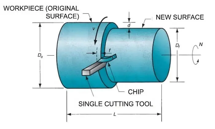
Turning is a machining operation in which a single-point cutting tool removes material from the outer surface of the workpiece that is subject to rotation along a horizontal axis in the lathe.
To turn on a lathe machine, the cutting tool is fed linearly in a direction parallel to the axis of rotation of the clamped workpiece, as shown in the figure below.
Hence, one can say that a machine used for turning and other machining operations such as facing, drilling, chamfering, boring, threading, and knurling, among many others, in which the workpiece rotates along its axis and a single-cutting tool feeds it linearly is called lathe machine or lathe.
Lathe tools include cutting tools such as turning tools, parting tools, boring tools, threading tools, knurling tools, drilling tools, and others.
Broadly speaking, there are two types of lathe: metal lathe and wood lathe. Both are similar in concepts and construction yet have certain key differences specific to operation: A metal lathe is used for cutting, shaping, and machining metal workparts; whereas a wood lathe (or woodcraft lathe) is exclusively designed for machining (mostly turning and shaping) wooden objects such as bowls, spindles, decorative items, and others.
The present article is dedicated to metal working lathe.
In its working, the lathe provides needful power to the workpiece for rotation as well as to the cutting tool for feeding at a specific rate and depth of cut.
Main Parts
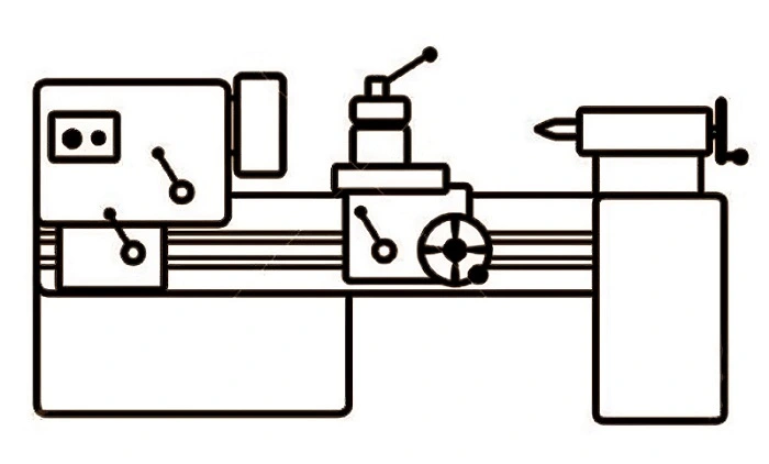
Lathe is a versatile machine tool that is used worldwide to carry out multiple machining operations. It is the most simple yet highly useful engineering tool used in small to large-scale industries. It is manually operated and is widely used to meet small to medium operational needs. It is shown schematically below.
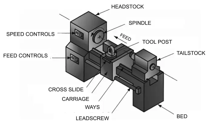
In the sketch illustrated above, the main parts of the lathe are labeled and are described immediately below:
- SPINDLE: It is used to hold the workpiece. It rotates during the machining process.
- HEADSTOCK: It contains the motor or drive that supplies power to the spindle for rotation.
- TAILSTOCK: It lies opposite to the headstock. Its purpose is to support the free end of the workpiece during the machining process.
- TOOLPOST: It is used to hold the cutting tool of the lathe.
- SADDLE: It has an H-shaped geometry. It is used to support the carriage, the tool post, and the compound slide. Or, fundamentally, it acts as a mount to hold the tool-post.
- CROSS-SLIDE: The tool-post is fastened to the cross-slide. It provides lateral movement to the cutting tool, which in turn determines the depth of the cut.
- COMPOUND SLIDE: Unlike straight or perpendicular cutting-feed provided by carriage and cross-slide, respectively, the compound slide is used to machine the workpiece at a desired angle. It is mounted on the cross-slide and is provided with the compound rest.
- CARRIAGE: The cross-slide is assembled into the carriage. The cross-slide moves at right angles to the principal direction of travel of the carriage.
- WAYS: Carriage slides along the ways of the Lathe. During the machining process, the carriage that holds the tool in the tool post feeds the workpiece while walking on ways parallel to the axis of rotation. In short, it forms the track over which the carriage rides. They are made with absolutely great precision to ensure the parallelism between the ways and the axis of the spindle.
- BED: It provides a rigid frame to the whole machine. Ways are built and supported into the bed of the lathe.
- LEADSCREW: It is also called a power screw or a translation screw. It feeds the carriage.
- GEARBOX: It is used to vary the speed of the rotating spindle. It consists of a set of enmeshed gears whose function is to provide different speeds to the rotating spindle or the work during the machining process.
- CHUCK: It is used to hold (or tight-grip) the work part. It is available in 3-jaw or 4-jaw configurations. It is tightened or loosened with the help of the chuck-key.
- CHIP PAN: It is a metal pan that is used to collect the chips produced during the machining process.
- APRON: It is used to provide automatic feed during machining. It is coupled with the feed rod for the auto-feeding of the cutting tool. It is mounted on the saddle and is internally connected to gears, levers, and other key components imperative for automatic machining.
- HANDWHEELS: There are three handwheels in a conventional lathe: one for carriage and the other two for tailstock and cutting tools. They are used to control the movement of the three elements of a lathe, as mentioned earlier, by manually rotating the wheel by its shaft.
- COOLANT SYSTEM: Modern lathe machines are provided with a coolant system to cool off the hot area of the workpiece during machining, which causes heat and frictional forces to develop at the point of contact between the work part and the cutting tool. The coolant system consists of a tank containing the coolant (a cutting fluid), a pump, and a hose that is placed above the cutting area.
Lathe Working
The workpiece or the work is clamped in a chuck. The headstock supplies rotational force or torque to work held in the spindle. The cutting tool is fixed in a tool-post that, in turn, is fastened to the cross-slide, which is assembled to the carriage.
The carriage is powered by a lead screw, which converts the rotational motion into linear motion, which is fed to the cutting tool. When the carriage moves along the way, it feeds the tool in a direction parallel to the axis of rotation or spindle axis. It performs operations such as turning to form cylindrical geometries on the part.
When the cross-slide moves, it feeds the tool in a direction perpendicular to that of the carriage or along the radial direction to perform operations such as facing and so on.
Conventional Types of Lathe
1. Horizontal/Vertical Turning Lathe
Horizontal lathe is a machine tool in which the spindle axis is horizontal. It is used when the length of the workpiece is larger than its diameter. It is described above in detail. Whereas the vertical type is the one in which the spindle axis is vertical. It is used when the diameter of the workpiece is larger than its length. Vertical turret lathe (VTL) is one such type. It is designed to have a vertical orientation and a turret-style tool holder for retaining multiple lathe tools (cutting tools).
2. Toolroom Lathe
It is a lathe that is provided with a range of spindle speeds and cutting-tool feeds. It is used in the fabrication of precision parts, such as for tools and fixtures.
3. Speed Lathe
It is simpler in design as it has no carriage, cross-slide, and, therefore, lead screw. So, how is the cutting tool supported? It is held by the operator using a take attached to the lathe for support. Though it is designed to have limited speed settings, its speed is higher than that of a toolroom lathe. It is used in applications such as wood turning, metal spinning, and polishing.
4. Turret Lathe
It is a manual lathe. It has no tailstock. Rather, it is provided with a turret that holds up to six tools. The turret is indexed to use tools one after the other according to the machining sequence. In short, it is a machine tool in which a four-sided or six-sided turret replaces the tool post to perform cutting operations in an ordered manner. It is used where mass production is required.
5. Chucking Lathe
The chucking lathe has a chuck to hold the workpiece in its spindle. It has no tailstock, due to which the workpiece cannot be mounted between the centers. Its operation is similar to that of the turret lathe. However, cutting tools are fed automatically rather than manually by the operator, whose only task in the present case is to load and unload the part. A chucking lathe is sometimes called a chucker.
6. Bar Lathe
It is provided with a collet (a unique type of chuck) to hold the workpiece with large length-to-diameter ratios called a bar stock. Automatic feeding and indexing popularize it as an automatic bar lathe. It is available in single-spindle and multiple-spindle design variations.
7. CNC Lathe
It is a modern lathe in which the automatic control over the cutting tool movement/feed is achieved by a special program of instructions written in a computer language known as G&M codes. It provides a sophisticated means to control the cutter’s movement compared with its non-CNC counterpart, such as a chucking machine in which cams or other mechanical devices are used for such purposes. It is capable of cutting complex geometries on the workpart with fully automated machine control.
In addition to the lathe types, one popular type among hobbyists and DIY enthusiasts is a mini lathe which is a compact and portable construction for metalworking, woodworking, model engineering, and other precision machining projects on a small scale.
Lathe Specification
The size of the lathe is determined by the swing as well as the maximum theoretical length of the workpiece.
- Swing designates the maximum diameter of the workpiece to be machined and is twice the vertical distance between the spindle center-line and the ways. But, in actuality, the swing is less than the distance mentioned above because there are carriage and cross-slide assemblies on the way.
- The distance between the headstock and tail-stock centers determines the maximum length of the workpiece.
As an example, a 9″ x 30″ lathe can machine a workpiece with a maximum diameter of 9 inches and a maximum length of 30 inches.
Machining Operations on Lathe
In the following section, let’s discuss different machining operations that are performed on a workpiece in the lathe.
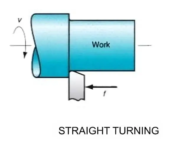
1. Turning
Turning is a machine operation in which different geometries are cut at the outer surface of a workpiece. In contrast, the workpiece rotates along its axis, and the cutting tool feeds it axially at a defined rate and depth of cut. The figure below shows a straight-turning process.
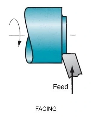
2. Facing
It is a machining process in which a flat surface of the rotating workpiece is produced. The cutting tool is fed radially into the workpiece at one end, thereby chipping off the metal radially. It is illustrated below.
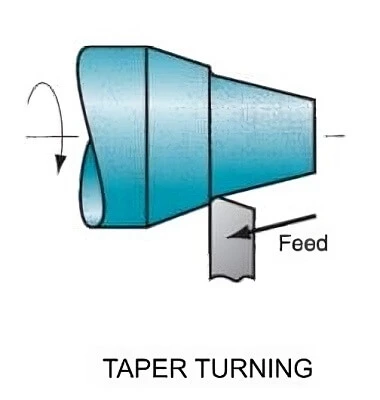
3. Taper Turning
It is a machining process in which the tapered cylinder or a conical shape is cut on the workpiece. The cutting tool is fed at a defined angle to machine a final cylindrical shape, as illustrated below.
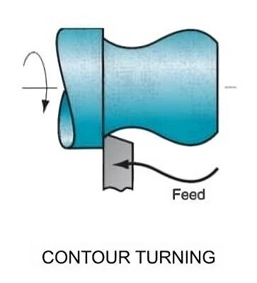
4. Contour Turning
It is a machining process in which a contoured profile is cut on the surface of a rotating workpiece. The cutting tool is fed neither parallel nor angular to the axis of rotation of the workpiece. Rather, it follows a contoured path as per the drawing on the turned workpiece as illustrated below.
5. Form Turning
It is a machining process in which the specific shape of the cutting edge of the cutting tool is cut on the workpiece. This process is also known as forming. It is illustrated below.

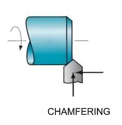
6. Chamfering
It is a machining process in which the cutting edge of the cutting tool is used to cut an angle at the corner of a cylindrical workpiece. The formed cut is called a chamfer.
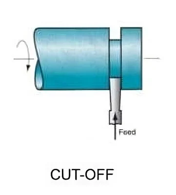
7. Cut-off
It is a machining process in which the tool is fed radially into the workpiece at a specific point along its length to cut off the end of the part. This process is also known as parting.
8. Threading
It is a machining process in which threads are cut on the outer surface of a cylindrical workpiece. A pointed tool is pressed against the surface, and a large effective feed rate is provided by a lathe along the length of the workpiece or in a direction parallel to the axis of rotation of the work part. The process is shown below.
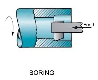
9. Boring
It is a machining process in a lathe in which an existing hole is enlarged. The boring tool is fed linearly to the workpiece in a direction parallel to its axis of rotation, as shown below.
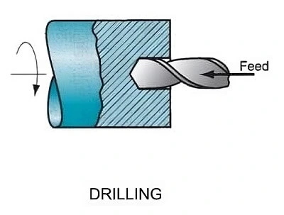
10. Drilling
It is a machining process in which a hole is machined into the rotating workpiece. The cutting tool is fed linearly along the axis of rotation, as shown below.
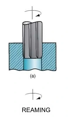
11. Reaming
It is a machining process in which, through a tiny cut, the accuracy of an already bored hole is increased. It is performed to enlarge the existing hole to provide a better tolerance on diameter as well as to increase surface finish.
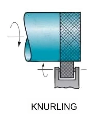
12. Knurling
Strictly speaking, it is not a metal-removing process. It is a process in which a cross-hatched pattern is produced on the outer cylindrical surface of a workpiece, as shown below.
I am the author of Mechanical Mentor. Graduated in mechanical engineering from University of Engineering and Technology (UET), I currently hold a senior position in one of the largest manufacturers of home appliances in the country: Pak Elektron Limited (PEL).